
-
Your Responses - Share & Have Fun :)
-
 Fried chicky, taters and corn. Full now. And no skippy' S WAS HARMED!
 -
By Macgyver55 · Posted
Wish I could take credit, but one of my cabin neighbors took this one… -
 Spooky! I would have missed this if it wasn't for the first trick or treater.
 -
-
-
-
-
-
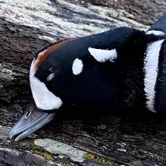
Was at the Shagawa lake boat launch and these two ducks came right up to me. I think someone has been feeding them. I also noticed that one of them has an eye that is partially shut.
-
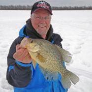
By snagfinder · Posted
I appreciate that. I actually stopped last night but I didnt get back to town til 5:45 and you were closed. Were open when I went by to bring the girls to school this morning so I grabbed eight packs. Probably be way to many dont remember them being so big.
-
-
Topics
-
Recommended Posts
Join the conversation
You can post now ↓↓↓ or ask your question and then register. If you have an account, sign in now to post with your account.
Note: Your post will require moderator approval before it will be visible.