
-
Your Responses - Share & Have Fun :)
-
 except for some mater plants i need to get from my brother.......garden is all planted!!!!!!!!👍
 -
-

-
-
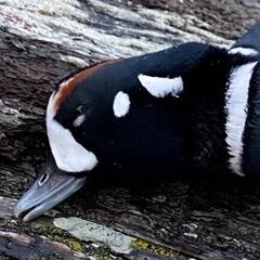
 yeah colors are interesting for sure, I think the rounded ears instead of pointed indicate wolf as well? coyote would have narrower snout as well.
 -

-
Based on the long snout and overall color.....I think that it is a young Timberwolf.
-
I have only seen wolves in our yard before. Last night this guy showed up. I am thinking it was a coyote. What do you think?
-
-
-
-
Topics
-


Recommended Posts
Join the conversation
You can post now ↓↓↓ or ask your question and then register. If you have an account, sign in now to post with your account.
Note: Your post will require moderator approval before it will be visible.